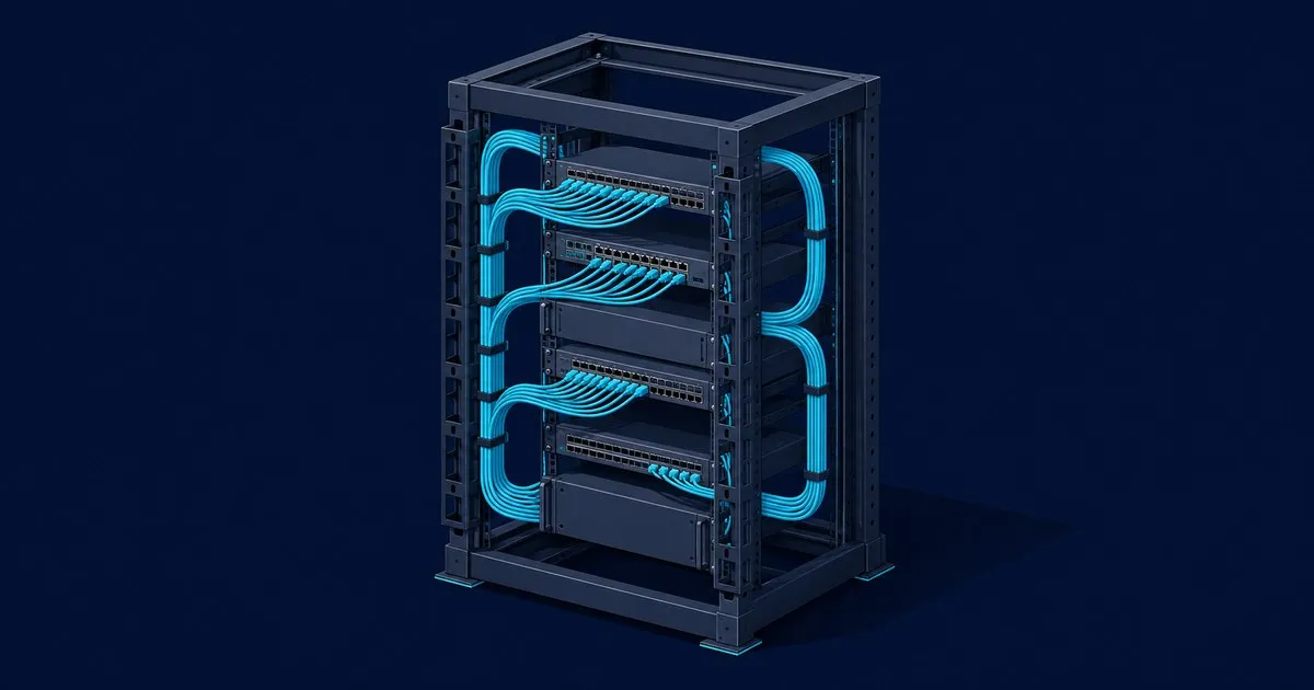
How to Cable Manage a Server Rack That Stays Serviceable
The order of operations for cable managing a server rack: layout, power and data separation, bend radius, hook-and-loop bundling, labels and airflow.
Most explanations of how to cable manage a server rack begin with straps and combs. The result is decided by three choices made before any cable goes in: where equipment sits, which side power runs down, and how many rack units the patch field gets. Get those right and the tidying is mechanical. Get them wrong and no quantity of hook-and-loop saves the rack at year three.
Fix the layout before buying a single cable
Schneider Electric’s White Paper 203 makes planning the first of seven steps, starting with whether cable enters from the top or the bottom. Bottom entry through a raised floor hides the far end of every run and forces a harsh bend at the tile. Top entry keeps runs traceable, and it fixes where the vertical managers, roof cutouts and PDU tails go.
Servers and UPS units belong at the bottom; trueCABLE’s rack wiring guide calls a top-heavy rack a serious danger. Switches and patch panels sit together so patch cords stay short, and the same guide budgets 2U of empty space above or below every 1U 24-port panel for cord management.
Count connections per device before choosing the rack, including management, redundant power and future ports. White Paper 203 says racks carrying real volumes of both copper and fibre need to be wider or deeper than standard, because fibre wants spools for slack and copper wants its own vertical channels. Cable bundle diameter covers the copper arithmetic.
With that connection count, calculate bundle diameter and tray fill before selecting the overhead pathway. Use the actual cable diameter and the tray’s usable dimensions, then check the manufacturer’s load and routing requirements.
Separate power from data, and copper from fibre
Bundle data down one rear side of the rack and distribute power down the other, crossing at right angles where they must meet. That is White Paper 203’s layout rule, and the reason is electromagnetic interference into twisted pair. For network racks the paper mounts power distribution on the rear cable channels, out of the data path.
Keep fibre out of copper bundles, because the weight of copper damages it. Fibre gets its own route, its own spools, and the top of any shared pathway.
Bend radius and bundling are what damage links
The cited bend-radius reference describes four times outside diameter for four-pair UTP and distinguishes installed from pulling limits for fibre. Use the actual cable manufacturer’s requirements, including any stricter construction-specific limits. Fit a waterfall or radius guide at tray drop-outs and roof cutouts as White Paper 203 recommends. The interaction between bends and pathway size is covered in cable tray sizing and bend radius.
Nylon ties are the other link killer. Cinched tight they crush the jacket, and because they cannot be undone without cutting, every change adds another tie. White Paper 203 recommends hook-and-loop ties that open and refasten; trueCABLE says never to use nylon ties on patch cords. NVIDIA’s DGX SuperPOD cabling guide applies the same rule to production AI racks: soft hook-and-loop instead of plastic, cables supported every 2 m or placed in trays, and cables tied to the rack structure so connectors carry no strain.
Patch cords get a defined path, then a length
Buy patch cords after the layout is fixed. White Paper 203’s routing rule is horizontal from the panel or switch to the side of the rack, then vertical in the side channel, never across the front of a switch where fan trays come out. A horizontal manager beside each panel gives every cord a defined path and a known length, so it can be bought to length instead of coiled.
At the rear of servers a cable management arm holds the slack a sliding chassis needs. Cisco’s C220 M4 installation guide puts the arm 5.4 in (137.4 mm) behind the server, 35.2 in (894 mm) overall, so check rack depth and PDU position first. White Paper 203 warns that arms can form an “air dam” across the exhaust, so fit them only where servers are opened often.
The rear of the rack is an airflow path, not storage
Cisco’s UCS 5108 chassis guide requires the rear exhaust to be unobstructed for at least 24 in (61 cm), explicitly including obstruction by messy cabling, and names the failure mode: failed DIMMs and seemingly random shutdowns once internal temperatures exceed specification. Cable belongs in the side channels and on the rails. Nothing hangs across a fan.
Fill every empty U with a blanking panel, and use brush-strip panels where cables must pass front to back; both are White Paper 203’s sixth step. At homelab scale, a PoE switch feeding a building’s access points is a heater, and budgeting its PoE load belongs in the same plan as keeping its exhaust clear.
Label both ends, then write it down
ANSI/TIA-606-C requires a legible, permanent identifier at both ends of every cable and on every patch panel port, near-end termination first. Silver Fox’s compliance guide puts the label within 300 mm of the termination and expects it to stay readable for the installation’s service life, typically 10 to 15 years.
White Paper 203’s seventh step is documentation and a change procedure. Skip it and a rack degrades one undocumented change at a time.
The order of operations
- Choose top or bottom entry; position vertical managers and PDUs.
- Heavy equipment low, switches beside patch panels, 2U of management per 1U panel.
- Data down one rear side, power down the other, fibre separate from copper.
- Permanent runs first, radius guides at every edge, hook-and-loop only.
- Patch cords bought to the defined path and length.
- Every empty U blanked, 24 in clear behind every exhaust.
- Both ends labeled to TIA-606-C, as-built documented.
Sources
- Schneider Electric White Paper 203, Planning Effective Power and Data Cable Management in IT Racks
- Cisco UCS 5108 Server Chassis Installation Guide, Installation chapter
- Cisco UCS C220 M4 Server Installation and Service Guide, Installing the Server
- NVIDIA DGX SuperPOD Cabling Data Centers Design Guide, Cable Management Best Practices
- trueCABLE, How To Wire a Server and Network Rack: Tips and Best Practices
- Elliott Electric Supply, Minimum Bending Radius for Cable (TIA/EIA-568 and ISO 11801)
- Brady, Cable Labeling Standards: ANSI/TIA-606-C
- Silver Fox Labeling, TIA-606 Cable Labeling: The Complete Compliance Guide
Related

Cable Basket vs Ladder Rack vs Solid Tray Compared
Wire basket, ladder rack and solid bottom cable tray compared on support, drop-out access, ventilation, load class and where each one is worth its cost.

Cable Bundle Diameter: How to Calculate Bundle Size
Work out cable bundle outer diameter from run count and cable OD, why real bundles miss ideal packing, and what the number is used for in a rack.

Cable Tray Fill Calculation: NEC Limits and Sizing
Understand cable tray fill calculation, NEC 392.22 limits, Cat6a capacity, bend radius, service loops and the rack layout behind a usable pathway.